|
|
|
This article was first published on the Pitlane Slot Car Club website www.pitlane.nzsca.co.nz |
Click on photos for larger view |
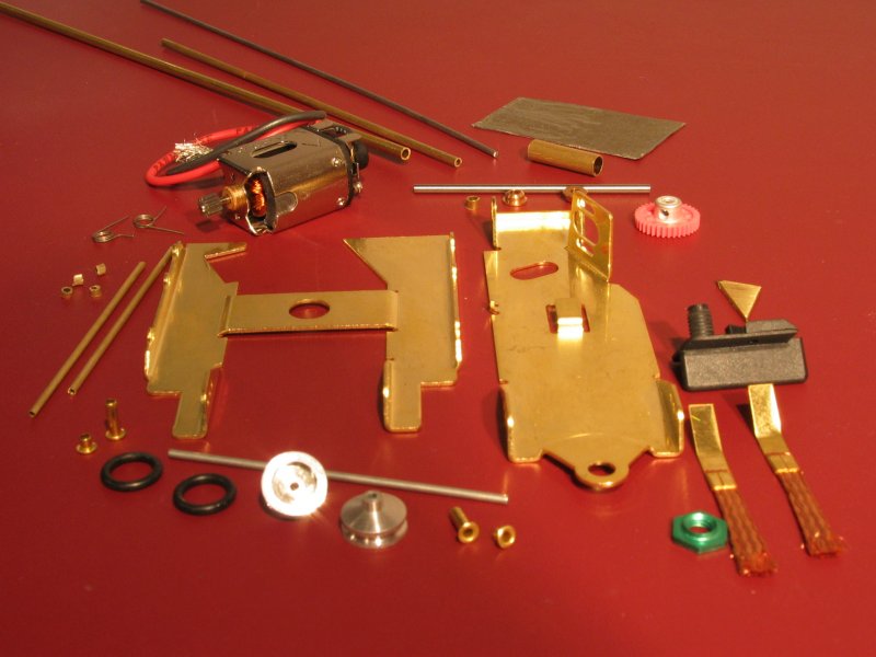
They do have a few small areas of concern but these can be easily overcome.
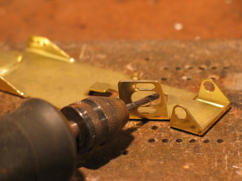
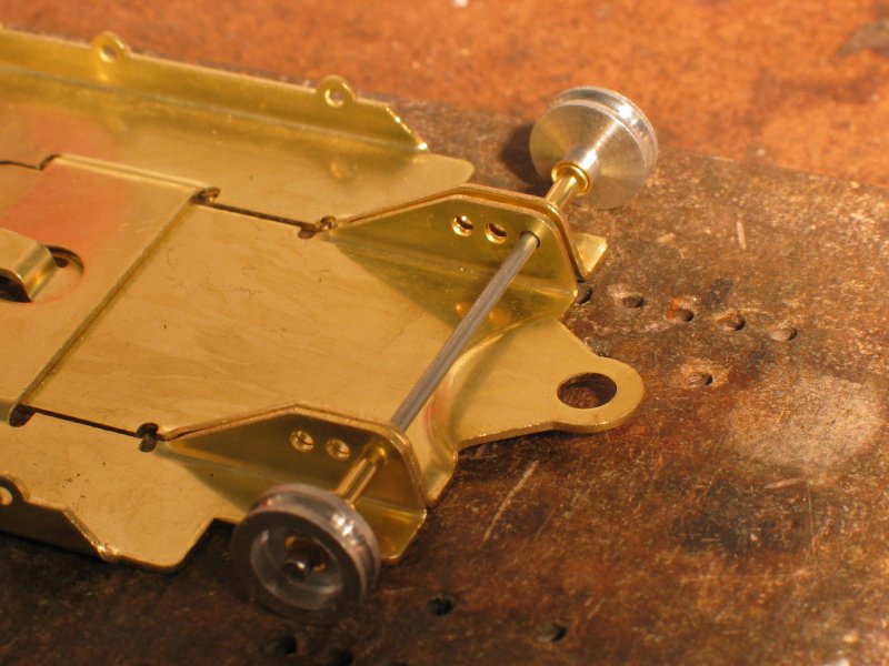
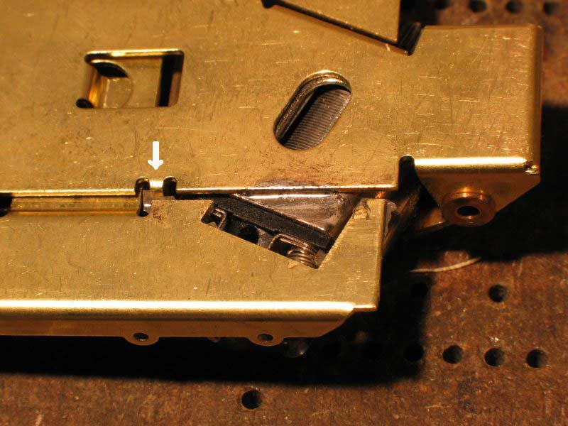
2. Place chassis parts on a flat plate and twist slightly to ensure both pieces are as flat as possible. 3. I’m assuming you know how to solder. Use acid flux whenever doing the structural soldering to ensure the solder “takes” to the metal. Don’t use flux on electrical connections. 4. Elongate the opening on the motor bracket taking care not to open the end (picture 2). Depending on the gear you are using this may not be necessary. 5. Cut a piece of 3/16” inner diameter brass tube to fit snugly between the rear uprights 6. Hold the 3/16”tube between the uprights and locate the oilites in their holes, slide an axle through the oilites to align them. Once everything is in place, ensure the axle is free to spin and slide. Solder the tube and oilites to the chassis (picture 3). Check that the axle still spins freely. I spend some time ensuring the axle lines up with both oilites. Resolder the oilites if necessary. Any friction here will rob us of speed. 7. Place the two chassis parts together and slide the front axle through one set of holes (picture 4). I recommend the front or middle sets. Slide the front axle spacers onto the axle, then the wheels (without their O rings at this stage), then the wheel retainers, which came with the chassis. Carefully solder the retainers to the axle ensuring the wheels are free to rotate.
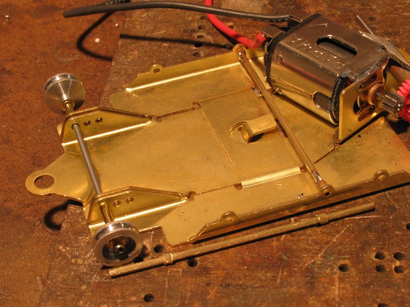
8. We now need to brace the front axle in order to stop it rotating. This is crucial, see above.
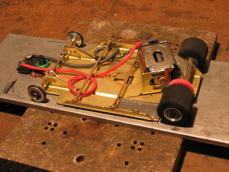
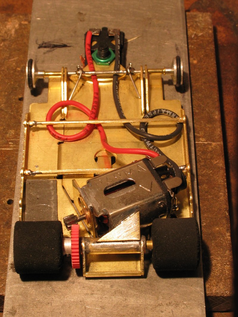
9. Locate the gear on the rear axle; slide the pinion onto the motor shaft. Place the motor into position and slide the motor rearwards and adjust the pinion to press against the gear. Note the position of the pinion on the motor shaft and solder. The outside edge of the pinion MUST always be outside the edge of the gear (see picture 10). If the edge of the pinion runs on the gear face the gear will wear very quickly.
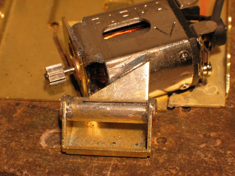
10. Clean the rear of the right hand sidepan and place some insulating tape on the top surface. This will prevent the endbell hardware shorting onto the chassis. I favour magic tape for this application. 11. Cut a triangular piece of brass strip (16 or 18 gauge does the job) and solder to the axle tube and motor as shown in picture 5. 12. Turn the assembly over and solder the endbell end of the motor case to the central chassis (picture 6).
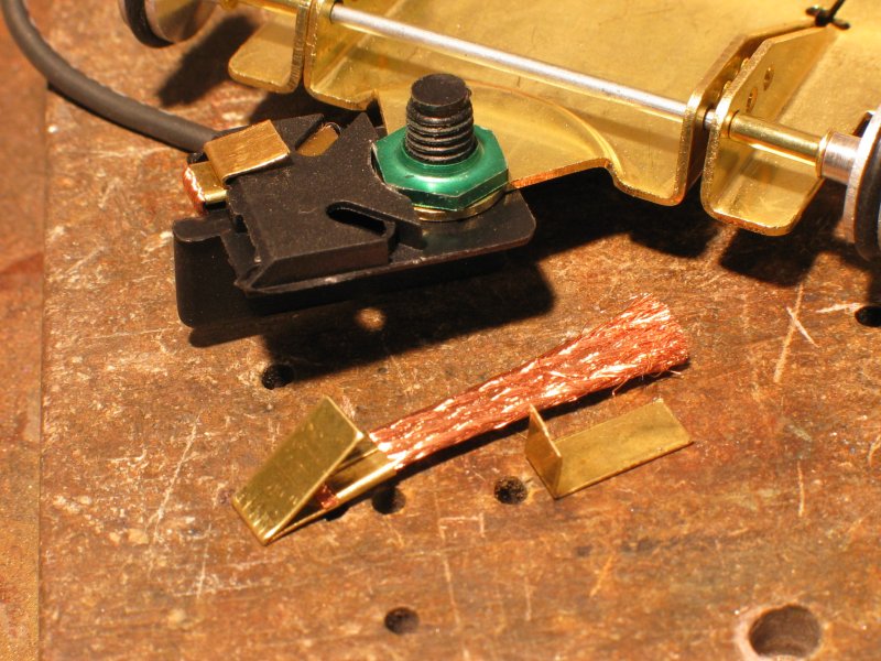
13. It is now time to decide how you wish to mount the body. 14. Take a pair of old braids with clips and cut to make a pair of tags (see picture 8).
15. Locate the guide and tighten the nut (not too much, make sure the guide is free to turn). Adjust the new braids to have the clip faces spread, insert the tags into the guide and then slide in the braids. Fold the braids under the guide and then fold the tags back over the top edge of the guide (picture 8). 16. Solder the motor leadwires to the tags. 17. Put the O rings on the front wheels and we are nearly ready to go. 18. THIS BIT IS IMPORTANT. Take the completed car and wash it thoroughly in hot water with a little dishwashing fluid. I use an old toothbrush to scrub everything. Rinse the whole assembly in hot running water and then dry. (Don’t worry about getting water in the motor; just flick it out.) The aim here is to remove all traces of the acid flux we used when soldering. 19. Now oil the front wheels, both ends of the motor and the oilites. 20. Slide the rear wheels onto the axle and tighten, the left hand wheel (looking forward – picture 10) will be close to the gear boss. Insert axle spacers between the bearing and the wheel on the right hand side (I use a piece 3/32” tubing about 2mm long). 21. Ensure everything that turns does so freely. 22. Bed in the motor brushes and the gear by running the car on lower power for around 15 minutes. Rev it occasionally. Run it backwards a couple of times on low power to help bed it the gear and pinion. 23. Time now to mount the body (a story in itself). I always sit the chassis on a block, which is narrower and shorter than the chassis, and then slide the unpainted body over the chassis. Mark the rear wheel arches and then cut these out. Reintroduce the body to the chassis and when you are happy it is sitting properly push pins through the body into the body mounting tubing or where the body clips will fit. Mark the lower edge of the body; remove and trim. Always aim to get the body as low as possible without fouling the wheels. Although the bodies are light they still affect the handling. 24. Most racers stick small amounts of lead to the chassis. The most popular places are at the back of the left hand sidepan, in the centre of the chassis just behind the guide pivot or on the front of the sidepans. |
|||||||||||||||||||||||||||||||||||||||||||||||||||||||||||||||||||||
 |
||||||||||||||||||||||||||||||||||||||||||||||||||||||||||||||||||||||
 |
||||||||||||||||||||||||||||||||||||||||||||||||||||||||||||||||||||||
 |
||||||||||||||||||||||||||||||||||||||||||||||||||||||||||||||||||||||
 |
||||||||||||||||||||||||||||||||||||||||||||||||||||||||||||||||||||||
 |
||||||||||||||||||||||||||||||||||||||||||||||||||||||||||||||||||||||
 |
||||||||||||||||||||||||||||||||||||||||||||||||||||||||||||||||||||||
 |
||||||||||||||||||||||||||||||||||||||||||||||||||||||||||||||||||||||
 |
||||||||||||||||||||||||||||||||||||||||||||||||||||||||||||||||||||||
 |
||||||||||||||||||||||||||||||||||||||||||||||||||||||||||||||||||||||
|
||||||||||||||||||||||||||||||||||||||||||||||||||||||||||||||||||||||